Outline
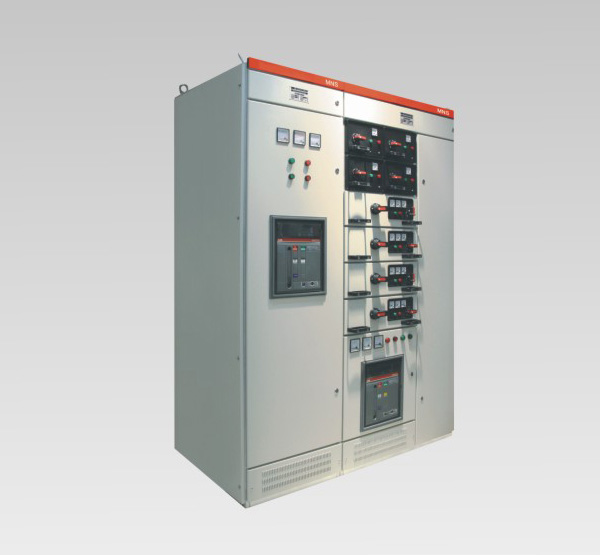
This series of low-voltage switchgear pumping this out is a standard factory-assembled modules (FBA) modular cabinet type.
This series of low-pressure pumping this out switchgear for power plants, substations, petrochemical, metallurgy rolling, transportation and energy, textile and other industrial enterprises and residential areas, high-rise buildings and other places, as the exchange of 50 ~ 60HZ, rated working voltage AC energy conversion 660V and below the power system of power distribution equipment, distribution and control purposes.
This device complies with G B2751.1 "Low-voltage switchgear" and JB / T 9961 "low-voltage withdrawable switchgear" national professional standards and in accordance with international professional standards IEC 349-1.
Normal environmental conditions
◆ The ambient air temperature is not higher than + 40 ℃, not lower than -5 ℃, and 24h average temperature does not exceed + 35 ℃.
◆ atmospheric conditions: air cleaner, the relative humidity at the highest temperature is + 40 ℃ not more than 50%, at a lower temperature allows a higher relative humidity, for example at + 20 ℃ to 90%, but sit it into account temperature changes may occasionally produce condensation.
◆ altitude less than 2000m.
Transport and storage ◆ The device is adapted to the following temperature: -25 ℃ to range between + 55 ℃ in a short time (less than 24h) up to + 70 ℃, in these devices should not suffer extreme temperatures any irreversible damage, and should be able to work under normal conditions.
◆ If the above conditions are not met, the user and the manufacturer should be resolved through consultation.
◆ When this device is used in offshore oil drilling platforms and nuclear power plants, should be separately signed a technical agreement.
Basic technical parameters
1, the electrical properties

2. The degree of protection
Compliance with IEC 5 29, DIN 4 0050 standard
IP30 protection for more than Φ2.5MM fixed
IP40 protection for more than Φ1.0MM fixed
IP54 for dust and spray protection in any direction
(Order IP54 protection rating should consult with the manufacturer)
Cabinet structure
Switchgear cabinet basic structural formula by C-sections assembled components. C profiles based on steel bending modulus E = 25mm mounting holes for the system. All cabinet and inner partitions are made of galvanized phosphate treatment. Four weeks doors, side panels will be used for high-voltage electrostatic spray. Figure 1 shows the basic structure of the cabinet: cabinet basic dimensions shown in Figure 2. Table 1, Table 2.
Switchgear type
1. The cabinet power distribution center (PC): can Emax, MT, 3WN, AH, ME series circuit breaker.
2. The motor control center cabinet (MCC): assembled by the size of drawers made of each circuit using high off the main switch or rotary molded case circuit breakers with fuse load switch. Automatic power factor compensation cabinet (with manual, automatic and remote power factor compensation device)
A power distribution center (PC) cabinet

B motor control center (MCC) cabinet

C-sections composed of cabinet structure (Figure) 1

Cabinet diagram (Figure) 2

Partition cabinet design
• Power Distribution Center (PC)
(1) .PC cabinet is divided into three compartments;
Flat busbar compartment: water at the rear of the cabinet;
Energy unit compartment: Power to the left in front of the front upper cabinets or cabinets;
(2) separate measures:
Between flat busbar compartment with water functional unit compartment separated by steel plates.
Separated by a polyphenylene ether flame retardant plastic housing compartment and between the loop-control function unit compartment.
(3) cabinet installed ACB, can achieve manually operated outside the cabinet under the closed state, open and close observation of the state of the circuit breaker and the positional relationship between the operating mechanism and the door off the circuit breaker in the sub test position or in the working position.
(4) Design between the main circuit and the auxiliary circuit into the separator structure, instrumentation, and other buttons and lights an auxiliary electrical unit, are mounted on a plastic plate, a rear plate with a flame retardant polyurethane foam plastic made of ester cover and the main circuit separation.
• power distribution center withdrawable motor control centers and low current (MCC)
Withdrawable, CC pumping cabinet is divided into three compartments, namely cabinet level after the bus compartment, front compartment ministry cabinet functional unit to the left of the front of the cabinet to the right of the cable compartment. Horizontal busbar compartment and can be separated between the power unit room with flame retardant foam plastic plates separated by function, the cable compartment and the level of bus compartment, separated by steel compartment between the functional units.
MCC (motor control center M) drawers divided into the following five kinds:
• 8E / 4: High 200 × 150 × depth 400mm width
• 8E / 2: High 200 × 300 × depth 400mm width
• 8E: High 200 × 600 × depth 400mm width
• 16E: High 400 × 600 × depth 400mm width
• 24E: High 600 × 600 × depth 400mm width

• After the outgoing cabinet structure
In order to reduce the width of the switchgear arrangement designed to appear, the main bus level switchgear mounted on top of the switchgear, the latter part of the cabinet for cable compartment, inlet and outlet cables are connected to the cable compartment after the cabinet. Switchgear front chamber for device installation functional unit switchgear. The system is designed on the side of the switchgear cabinet to move the cable compartment after compartment, greatly reducing the width of the switchgear arrangement to further meet the requirements of the spatial arrangement of the substation.
Feeder cabinet cabinet width 600mm, depth 1000 / 1200mm, top independent main busbar chamber and device isolation chamber. Front chamber effective means mounting height 72E (E = 25mm), through multifunction board with rear cable isolation room, full use of the installation space switchgear, compact unit configuration flexibility. The back of the cable compartment with doors, installation and easy maintenance.
Line width of the cabinet by cabinet to determine the current incoming unit, recommended width of 400/600/800 / 1000mm, cabinet depth 1000mm.
Bus system
Switchgear main bus can be configured two groups, installed in the rear of the bus room switchgear. Second group on the bus can be installed in the upper and lower back cabinet respectively. Line according to needs, the upper and lower two groups busbars may adopt different or the same cross-section material. Two separate power supply can also be powered in parallel, or be used as a backup power supply.
Distribution bus (vertical bus) assembled in flame retardant plastic functional board, connected through a special connection piece and the main bus. Can prevent the arc discharge caused, but also to prevent human contact. Cabinet with a separate PE and N neutral conductor grounding system. Both throughout the device, mounted on the bottom and right side of the front cabinet. Each loop ground or near zero can join. The entire bus system is installed as shown in Figure 3. Shelves structure of all self-tapping screw connection, with high ground reliability.
Neutral bus and the neutral bus bar protection mounted in parallel and vertical in the lower compartment of the functional unit installed in the cable. Between the N line and PE lines as separated by insulators, the N line and PE lines are used as if between the two conductors shorted Serve PE / N lines.
Protection circuit device installed by a separate arrangement and throughout the length of the PE wire (or PE / N line) and a conductive structure of two parts. Means metal structure, with the exception of the table and the door seal plate, the rest have been galvanized, at the junction structure, have been carefully designed to make it through some of the short-circuit current.
Protective earthing system
Protection circuit device installed by a separate arrangement and throughout the length of the PE wire (or PE / N line) and a conductive structure of two parts. Means metal structure, with the exception of the table and the door seal plate, the rest have been galvanized, at the junction structure, have been carefully designed to make it through some of the short-circuit current.
Auxiliary circuit and cable ducts
At the top of the functional unit compartment is equipped with auxiliary circuit cable slot, the slot can be placed between the cabinet cable combined utility power lines.
Cable and control cable
Withdrawable components on one side, a small room equipped with cable wiring devices and terminals for outgoing cables, control wiring line fit between components. Inlet and outlet cable and control cable wiring devices arranged on the rail on the right side of the cable compartment. Located in the rear of the main circuit terminals, control terminals are located on the front line of the 45 ° direction. Terminal control line screw terminals or plug-in available lines connecting the nose or with copper fittings to connect. Withdrawable on adapter assembly is less than 63A of the main circuit terminals with PE terminals.
Security System
Each cabinet has one or a group of flame-retardant plastic functional board, installed between the main bus room and electrical room, whose role is to prevent accidents caused by a short circuit between the arcing due to failure caused by the switching element and the bus, take a strict quarantine measures.
Between the upper and lower drawer with galvanized metal floor vents are isolated, smaller 8E / 4,8E / 2 drawers around it are flame-retardant plastic parts, so there is a strong insulation between adjacent circuits isolation. Cabinet using a variety of plastic components to support the live parts, these components halogen-free and has a leakproof performance CT1300 grade above.

Drawer type

Electrical and mechanical interlock drawer
Drawer unit has reliable mechanical interlock position by operating the handle control, with clear and accurate closing, testing, withdrawal and isolation position. Function operating mechanism shown in Figure 4, Figure 5. To strengthen the installation precautions, can be added after the operating handle positioning padlock, plus up to three locks, see left.
Must be strictly in accordance with 4, showing the operation and location of the operation switch functions listed in Figure 5, or easily damaged drawer unit structure in place, when your users attention.

Operating diagram of the switching function

Combinations diagram (Fig. 6)

Installation diagram (Figure) 7

Bus bridge installation diagram (Figure) 8