Scope
JY1N-40.5 septum indoor sets of devices (Shift Z open) type between AC metal enclosed switchgear (hereinafter referred to as switching equipment) three-phase AC 50Hz single busbar mother singlet and system for receiving and distributing network 35kV network electric energy. This switch device performance meets GB390I6E and C29 standard eight prospective requirements, preventing sliding with a load circuit breaker to prevent misclassification error breaker to prevent closing the circuit breaker in the closed position when the grounding switch, to prevent mistakenly charged compartment room, to prevent the charged closing earthing switch when the "Five Anti" interlock function.
The company's products compared with similar products, with the following characteristics;
1 can be equipped with the excellent performance of ZN85 * 40.5 fully insulated vacuum circuit breakers, screw nut transmission, clutch, with good arc performance, easy operation, maintenance and other advantages.
1.2 Selection creepage distance, excellent insulation properties of current transformers, voltage transformers, post insulators, CMC material insulating spacers and contact box, the switching equipment insulation level can be improved.
1.3 transformer can be used dry-type transformers, oil-free, flame retardant, running economy, and must maintain.
Model meaning and classification

Normal conditions of use:
· Ambient air temperature: -15 ℃ ~ 40 ℃;
· Altitude: not exceed 1000m;
Humidity conditions:
Daily average relative humidity less than 95%
Water vapor pressure on average less than 2.2kPa;
Monthly average relative humidity less than 90%;
Water vapor pressure on average less than 1.8kPa;
· Earthquake intensity: no more than 8 degrees;
· No fire, explosion, serious contamination, chemical corrosion and severe vibration.
Special Conditions:
When more than GBⅡ022 normal conditions of use specified user please consult with our company.
The main technical parameters
Switch technical parameters of the device (see Table 1)

*: When equipped with vacuum circuit breakers and SF6 circuit breakers ZN23-35 no such series
· ZN85-40.5 vacuum circuit breaker technology parameters (see Table 2)

Product Structure
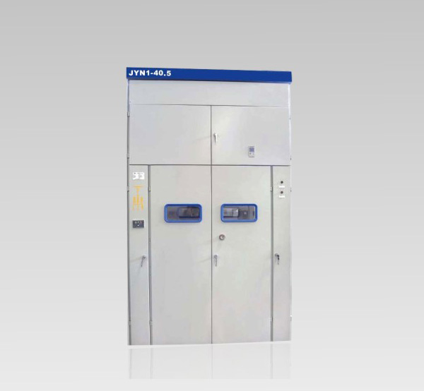
JYN1-40.5 (Z) interval remove AC metal-enclosed switchgear structure belonging to the interval, which welded from steel and steel plate bending from the cabinet and handcart two major components. Withdrawable circuit breaker can be classified according to their use, arrester handcart, isolating handcart, "Y" shaped connection voltage transformer handcart, "V" shaped connection voltage transformer handcart, single-phase voltage transformer trolley and the trolley station transformers and other seven, which has ZN85-40.5 vacuum circuit breaker circuit breaker, ZN23-40.5 vacuum circuit breaker and SF6 circuit breaker. Switchgear and trolley dimensions (see Figure 1), the internal structure diagram (see Figure 2)


Switching equipment according to use separate into several functional units, are described as follows:
· Housing
Switchgear enclosure has IP2X degree of protection to prevent a diameter greater than 12 mm inside objects close touch live parts and used part of the movement.
In addition to the high-pressure intervals door hinges with metal braided copper wire is also used outside the door and the cabinet is connected. In the front and back of the case of the switching devices are equipped with inspection window to observe the operation of the equipment inside the switchgear.
· Used room
Lower part of the front of the device switch two doors open, which is the handcart. The upper chamber, separated by an insulating partition between the lower chambers contacts between Roof main bus and provided with a metal bulkhead. There handcart handcart bottom rail, central handcart grounding in both tracks. To prevent condensation heater specialized settings are also located on the right side of the chamber.
· Main bus and the isolation chamber contacts
And on a main bus isolation switch contacts in the upper chamber devices. Main lines arranged in a triangular arrangement on the upper post insulator flip. Immediately below the main bus stand for the isolating contacts, which can be a current transformer with a contact, it can be a pillar or wall bushing insulators with contacts, depending on main connection scheme may be.
· Contact isolation room
Contact isolation room on the lower contact isolation room, separated by a separator between the two, which in addition to the current transformer for installation or post insulators seat outside contacts, or contact the busbar earthing switch is also located in the chamber .
· Insulation barrier and insulation valve
Withdrawable switchgear room between contacts and isolation rooms with cable room, equipped with a partition made of insulating material and the installation of SMC SMC insulation valve on it. Partitions and insulation valves have IP2X degree of protection.
· Earthing switch
Grounding switch as a variable element may be trade-offs needed project, when outgoing circuits needed overhaul breaker retreat isolated position, close the earthing switch to ensure safety.
· Electric display device
Live shows are variable element, its role in the case of switching equipment is not equipped with a voltage transformer and can directly reflect the charged case of high-voltage feeder lines. So that the grounding switch is closed before the feeder line can be determined in advance whether or not charged.
· Grounding conductor
Across the switching device in the entire width direction of the copper ground conductor mounted on the switch in the bottom of the device. The connection between the two, and is equipped with a factory prefabricated devices and connectors can be installed inside.
· Auxiliary circuit installation equipment
The upper part of the front of the device is provided with means switching auxiliary circuits equipment meter relay room door and shake the door structure. Both sides of the room there is a small bus control lines through holes and fixed with cable clamp, the left has a small bus terminal group, above and below are equipped to go trough. Meter relay room with doors and high-pressure intervals separated by a partition.
· Terminal compartment
Room is located on the right side at the front of the switchgear, auxiliary circuit terminals installed in the central group of the chamber. Top of cabinet lights and switches; provided below ground M12 bolt for auxiliary circuit ground use: The right for users with fixed control cable clamp bracket.
· Secondary plug (Block)
Cable trolley and switch between devices are installed in the plug and through the switching device installed in a socket on the trolley car to push forward now to the real. "Hand test position" should plug in. When the handcart Exit "Test Position"; should be unplugged.
Small Bus
Switching devices with a small bus terminal group 15, according to the provisions of rationing small bus conductor preparation by the user.
· Condensation control
There are large regional variations in humidity or temperature occasion, when switching equipment out of operation, it is possible to produce condensation. Thus installed condensation control within the switching equipment, with the temperature increasing method, such that vapor in the air can not condense.
Auxiliary loop control cable channel
Switchgear auxiliary circuit control cable channel (cable channel starting secondary role) located above the relay room, the control cable from the cable channel aligned left or right of the switchgear introduction,
After the bottom of the bottom of the switching device or terminal compartment left door of the introduction of small channels. The passage through each switching device.
· Cabinet lighting
Withdrawable switchgear room with a lamp 220V, 100W lights, lights and switches are mounted above the terminal compartment, the operator must replace the lamp light switch or open the terminal room door before proceeding.
· Product installation instructions;
· Product certification;
· Factory inspection report;
· Product secondary wiring diagram;
· Product Packing List.
· Equipment and spare parts inventory;
· ZN85-40.5 vacuum circuit breaker operating handle, charging handle contract sets the amount of 10 below, with each set of five; more than 10 units, each additional 10 units, plus a set).
Ordering Information
· The main circuit of Figure knot line system or main circuit diagram;
· Switching equipment layout plan, bus number and size of the bridge;
· Control, protection circuit electrical schematics, terminal layout diagram;
· Main bus specifications;
Model · Each switch device installed in a variety of major electrical equipment, specifications, quantity;
· If you have special requirements, please attach a detailed explanation.