Outline
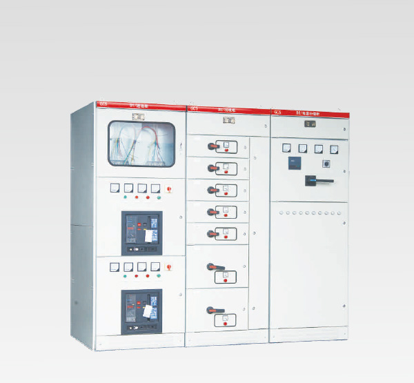
G GCS device is suitable for power plants, petroleum, chemical, metallurgy, textile, high-rise buildings and other industries and distribution systems. High degree of automation in large power plants, petrochemical system, computer interface requirements and place, as a three-phase AC frequency of 50 (60) Hz, rated working voltage of 380V (400V), (660V), rated current 4000A and below the hair, the power supply system of distribution, motor centralized control, low voltage power distribution equipment used in reactive power compensation.
Type Meaning

Performance
Design of the device meets the following criteria
• IEC439-1 Low-voltage switchgear and control equipment
• GB 7251 Low-voltage switchgear
• ZBK 36001 low-voltage withdrawable switchgear
Basic parameters

Main structure
• The main frame adopts two side openings 8MF type steel, steel, respectively, the modulus of 20mm, 100mm mounting holes and φ9.2mnl, the internal installation flexibility.
• The main frame assembly design in two forms, the whole assembly structure and parts (side frames and beams) welded structure for users to choose.
Each function room
• devices are isolated, its compartment is divided into functional unit room, bus room and cable room. The role of chambers of relatively independent.
• With the level of the main bus-mounted cabinet level arrangement to enhance the ability of anti-electricity-powered bus, the main circuit device with basic measures of high short-circuit strength capabilities.
• cable compartment design allows the cable down and out are very convenient.
• Device Universal cabinet size series (see table below):

Functional unit
• drawer storey modulus of 160mm, divided 1/2 unit, Unit 1, 3/2 units, 2 units, 3 units of the five dimensions of the series. Unit circuit rated current 400A and below.
• a change in the height dimension of the drawer only changes its width and depth dimensions remain unchanged. Drawer unit having the same function as good interchangeability.
• Each MCC cabinets can be installed up to 11 units of a drawer or 22 1/2 unit drawer. One uses a versatile drawer unit above the rear panel.
• drawer into the outlet using the same specifications of the plug-piece structure of different sizes based on the current number of pieces.
• 1/2 drawer unit and adapter cable compartment using backplane structure ZJ-2-type adapter.
• drawer unit and adapter cable compartment divided by the current file with the same size rod or tube-type structure ZJ-1 adapter.
• drawer unit with mechanical interlock devices.
The main electrical components
• The main electrical components selection principles based on the introduction of technology into a series of domestic energy production, but also to meet the requirements of high performance devices.
• Power and feeder unit breaker primary election AH series, but also can choose other more advanced performance Schneider company's M series, ABB company's F series. AH-breaker with a good performance, compact, lightweight, and strong family characteristics. The price is relatively low, maintaining ease of use, the performance indicators to meet the requirements of the unit.
• drawer unit (motor control unit, part of the feeder unit) breaker primary election CM1, TG, TM30 series molded case circuit breakers, some choose MOELLER company's NZM-100 A series. These switches have a good performance, compact, short arcing or flashover, the characteristics of high technical and economic indicators, to meet the requirements of the unit.
• disconnectors and fuse switch disconnectors election Q series. This series of high reliability, breaking ability and can achieve a mechanical interlock.
• Fuse primary election NT series.
• choice of B series AC contactor, LC1-D series.
Device characteristics
• Increase the heat capacity of the adapter, additional temperature reduced significantly due to the temperature rise adapter connectors, cable head, spacer plates brought.
• between the functional units, the partition between the compartments clear, reliable, due to failure of a unit without affecting the other units of work, so that failures confined to a minimum.
• Bus flat-mounted arrangement enables dynamic thermal stability of the device, able to withstand 80 / 167kA short circuit current impact.
• MCC single cabinet cabinet number loop 22 times more to fully consider the needs of large unit capacity power generation, petrochemical and other industries automation motor group.
• devices in the cable compartment complete with the external cables, the cable can be up and down and out. Current transformer device to cable compartment, making installation and maintenance.
• The same power distribution system, you can match limiting reactors limit short-circuit current, stable bus voltage at a certain value, but also reduce the component parts of the short-circuit strength requirements.
• drawer unit has a sufficient number of secondary connectors (1 unit and above 32 pairs, 1/2 units of 20 pairs), to meet the computer interface and automatic control loop for the number of contact requirements.
Auxiliary circuit
Auxiliary circuit diagram is designed to meet the design point of order "power plant power plant design" and other provisions for power plants, substations Low plant (the) power systems and industrial enterprises, low-voltage distribution system within the high-rise building .
Auxiliary program sub-circuit the power line based on the main circuit scheme, the functional unit feeder (PC) and the motor feeder (MCC) controls the operation of the design.
Installation and Use
Products produced goods arrive after closing locations, we should first check the packaging is intact, identify problems and shall promptly notify the relevant departments to contract business records, jointly analyze the causes and make visas and deal with the aftermath. For not installed immediately and should be placed in the temporary custody order requirements appropriate place according to the normal conditions of use and electrical equipment, for safekeeping.
• Install the product should carry out the installation diagram (see photo). Basic channel and bolt bolted way when owned by the user. The main bus connection. As a result of surface transport, storage and other reasons is not required to flat after flat connections are tight.
• devices installed individually or as a column, its verticality and counter irregularities and gaps between cabinets deviation shall meet the following requirements.

• After installing the product inspection and testing before operation
(1) Check the cabinet paint or other covering material (eg spray) for damage, the cabinet is clean and dry.
(2) the electrical components of the operating mechanism is flexible, there should be no catching or operating force is too large phenomenon.
(3) Major appliances off the main and auxiliary contacts are reliable and accurate.
(4) drawer pull or draw-out mechanism should be flexible, lightweight, non-jamming and collision phenomenon.
(5) move out of the drawer or the structure of the centerline of the static contact should be consistent, should contact close contacts. Primary and secondary contact insertion depth shall comply with the requirements. Mechanical or electrical interlock interlock
Action should be installed properly set, lock or unlock should be reliable.
(6) the same size as the drawer can easily be interchanged without jamming and collision phenomenon.
(7) ground contact between the drawer and the cabinet should be in close contact, when the drawer is pushed in, the first contact with the ground contacts drawer than the main contact, ground contact when pulled over after the main contacts open.
(8) The meter scale tuning, transformer polarity change and should correct.
(9) fuse fuse specifications shall comply with the requirements of engineering design.
(10) The protection of ratings and setting should be correct and reliable operation.
(11) measured with 0100V megger insulation resistance value shall not be less than 1MΩ.
(12) connecting each bus should be well insulated supports, mounts and other accessories should be solid and reliable installation.
Cautions
(1) The device is not installed against a wall, positive operation, maintenance of low voltage distribution cabinet sided. Cabinet and maintenance access doors, the assessment must be qualified professionals to enter or open operation, inspection and maintenance work.
(2) The air circuit breakers, molded case circuit breakers after repeated division, especially after a short circuit switching, make contacts and generate local burn carbon substances, the contact resistance increases, should breaker manual maintenance and repair.
(3) After the installation and maintenance, must be strictly checked between each compartment, segregation between functional units, in order to ensure that this unit good functional compartmentalization to prevent the failure to expand.
Complete Set
Provide the following documents and accessories are supplied factory:
• Device List
• Product certification
• Owner's Manual
• The factory test report
• For electrical drawings
• door keys, the operating handle and spare parts under the contract
Installation Instructions • Key components
Ordering Information
Order contract contains the following:
• Product models include the entire main circuit and auxiliary circuit scheme No. No.
• The main circuit system combination sequence diagram
• auxiliary circuit electrical schematics
• cabinet components list
• circuit voltage, current, time and other tuning parameters
• inconsistent with the normal use of other special requirements
Installation diagram


Figure 3, MCC cabinet installation diagram